Building a fluidic control board
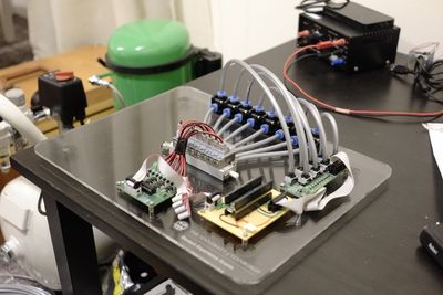
For my Master's project, I tried to use reinforcement learning to control a pneumatic robot. To do that, I first had to build an electropneumatic system to actuate it, similar to the Fluidic Control Board developed at Harvard. I made an 8-channel board which can provide up to 2bar of pressure with milisecond switching time, with precise pressure sensors monitoring each channel. The whole thing can be easily controlled with Python on a PC or Arduino on a microcontroller.
In this article I explain how I put it together. I tried to make it the guide that I wish I had when I was starting to design it. Here's a preview of what the final product can do:
This project was financed by a University of Edinburgh Student Experience Grant.
Components #
We're going to 'build' the system step by step. I'll mostly talk about what I chose for my system, but the choices that I made are not the only ones possible. I'll try to suggest cheaper/easier to get alternatives for most components. Let's start with the most basic part - the compressor.
Compressor #
Obviously, anything pneumatic needs a source of compressed air. A lot of soft robotic devices use diaphragm pumps, such as those:

They can be bought in small factors (which is good if you want to integrate a pump into a mobile system), but they're also quite expensive for their size.
On the other hand, they can be cheaply sourced from blood pressure monitors (or your favourite overseas trading website), and you can have a separate pump for each channel. With such a setup, you can more precisely dose the amount of air you push into it; this is quite helpful, because it's easier to control soft robotic devices by varying volume than pressure.
For use in a stationary system, or with a tethered robot, I think it is better to go with a proper compressor with a receiver tank, like the one you might see in a garage. The cost is comparable, and you can push much more air.
A small compressor is a useful thing to have in general. For example, if you connect the input of a compressor to a piece of tupperware, you'll get a poor man's vacuum chamber, which is very useful for casting soft robots out of silicone. Please don't try this at home.
I decided that I needed a quiet unit, because I ran most of my experiments in my flat. Compressors can get really loud (over 70dB, similar noise level to a vacuum cleaner). There are not many small, affordable, silent compressors available in the UK. I went for a Bambi BB24. It has a noise level of under 40dB, close to normal conversation. If I did not care about noise, I'd just get a simple workshop compressor for half of the price.
One important consideration is size. Most compressors are sized in
Below I show some back-of-the-envelope math that I did when sizing my compressor. Most readers will probably prefer to skip it and go straight to the next section. Here's a good specification for a compressor to run a typical 4-8 channel soft robotic system:
- capacity between 10-50
- it's highly recommended to have a storage tank with capacity
Compressors used for airbrushing are exactly within this spec. So are some used by dentists, but those tend to be much more expensive.
Compressor sizing calculations (feel free to skip this section) #
First, I determined the pressure my system would run at. Most soft robots are
inflated up to around
I needed this flowrate at
Which means that we need:
This is the peak consumption - I'm assuming that I'll be opening all
the joints at once. In reality, I'll be using a maximum of two
joints at a time, and I won't be actuating them that fast. My system will
probably draw a fifth of this flowrate, so a 15
This is much less than most workshop compressors can give you (they tend to
start around 200
It does not stop here. Most compressors cannot operate continuously, because they get too hot. That's why we put tanks on compressors - they act as a reservior of compressed air. We fill our tank up, and let our compressor rest as we deplete it. How big a tank do we really need? To know that, we need to consider the duty cycle of the compressor.
Bambi BB24 is rated for 50% duty cycle. It can be on half of the time, for up to 30 minutes (so the best we can do is 30 minutes on, 30 minutes off). The compressor will automatically pump the storage tank up to around 9 bar, turn itself off, and remain off until tank pressure drops to 6 bar. To exactly calculate how much flowrate we can get out of this 3 bar range, we'd need to resort to thermodynamics, but we can get a decent approximation with something much simpler.
We know from ideal gas laws that when the tank is at 9 bar (let's call it
of air at our output pressure.
When it's at 6 bar (
The amount of air we can get before the compressor switches off is simply the difference between the two.
If we want the compressor to only switch on every, say,
So now we can put this all together to calculate the required size of the tank:
In our case this is:
Which is quite a sizeable tank. My Bambi compressor comes with a 24l tank. Keep in mind that this is for an 8 joint system, and that I would like my joints to open in 0.3s. This is much faster than a typical soft robotic application. If I were to use just 4 joints, and I could live with a 1.5s opening time, I could use a 2.8l tank. Accidentally, many airbrush compressors come with 3l tanks.
How long would the compressor take to refill my tank? It pumps around three times faster than we're using up air, so it'll be much less than 5 minutes, and the compressor duty cycle is less than 50%.
A good rule of thumb is to get the largest tank you can fit. It'll offload your compressor and your ears.
Air treatment and regulation #
Air coming out of a compressor is usually quite low quality (it has a lot of airborne particles), and at a much higher pressure than we want for soft robotic applications. To deal with those issues, we need a regulator (to set the pressure), and a filter (to clean up the air). Sometimes, we also need a lubricator module; these generate a fine mist of oil, which some air tools and valves require to operate properly. Often, one would buy a combination Filter-Regulator-Lubricator (FRL) module for this purpose.
Actual choice of components would depend on the requirements of whatever hardware we'll be placing downstream. Here's how I chose mine.
The valves I chose to use for my system (more about them later) require air filtered down to 5μm, and are lubricated for life, so I did not need a lubricator at all (I got this data from the manufacturer's datasheet).
5 micron filtration can be achieved in a single step. A filter with a finer mesh would clog up too quickly if we exposed it to atmospheric air, so we'd usually have another filter in front of it to eliminate coarser particles. Think of sifting sand through finer and finer sieves.

Coincidentally, my compressor already came with a 10um filter-regulator installed. It's a SMC AW-20 module, from the SMC AC series. It's quite simple to operate: air from the tank passes through the filter at the bottom, and then a knob at the top can be used to set the pressure on the outlet. It would be good enough for my purposes, if it were not for two issues.
-
High pressure air expands as it leaves the tank, and the water vapour dissolved in it condenses. Water in your system can cause corrosion and other nasty things. Those small bowls below the filters in the picture are used to drain water, and they need to be emptied weekly if you use your compressor every day.
-
My compressor used a lot of oil for lubrication, and some of this oil could make its way into the air. In addition to making a mess, it could displace the lubricant im my valves, decreasing their lifetime.
I dealt with them by adding a mist remover (often called a dryer), after the filter-regulator. As the name implies, a dryer will remove tiny droplets from the air. I got a SMC AFM20 module from the same series as the regulator. This meant that I could get a dedicated clamp to join them and keep the whole assembly a little more compact.
If I didn't get a regulator with the compressor, I'd have ordered the whole assembly (filter + regulator + mist separator), for example SMC AC20C-A. For systems that operate at really low pressures, a precision regulator, like SMC ARP20, would be a good idea. I should have used one; I found that the output pressure of my AW20 can vary noticeably as the pressure in the tank changes when the output is set too low.
UPDATE: I added an ARP20 regulator and it really helps to stabilise the output pressure (the manufacturer claims that it'll be within 1% of the set value from 0 to 2 bar).
I did not talk about sizing a FRL system, because even the smallest ones are way too big for our use.
Valves and manifolds #
Now, that we have a source of clean, pressurised air, we need to control where and how much of it we want to send. In other words, we need a set of valves.
Valves #
We want to use electronics to open the valves, so we need direct-acting, solenoid-actuated valves. We also want our valve to be closed most of the time, so let's go with a normally closed (often abbreviated as NC) one.
Pneumatic valves come in a number of configurations; the most practical one for us is called two-position, three-way. This means simply that there are three ports on the valve, but only two possible positions of the sealing element. When the valve is closed (no current applied to the terminals), the outlet (our robot) will be connected to the atmosphere and deflated. The input is simply blocked off. When we open the valve, the input will be connected to the output, and our robot will inflate.
Valves should be sized depending on the flowrate. The calculations are quite involved (you need to calculate if your flow is slower than the speed of sound!), so I'll skip them here. Most valves on the market will be big enough for the flowrates we calculated above. I went with SMC V114A valves, the smallest ones in SMC's range, and they are still more than I really needed.
For those working on a smaller budget - search for "2 position 3 way valve" on eBay. I tried one of those £3 valves and it worked just fine. If you're using cheap valves, you can also skip filtering and drying.
Manifolds #
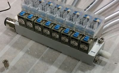
Because all the valves will be connected to the same source of air, we can connect all their inputs together. Some people choose to do it with tubes and fittings (more on those later), but we can get a much more compact layout if we put the valves on a dedicated manifold block.
A manifold is just a piece of metal with a lot of holes drilled through it, which connects appropriate parts of valves together. Not all valves are made to be mounted on a manifold (the V114A are). I highly recommend using one if you can afford to.
Another bonus to using a manifold is that we can use a silencer on the outlet of our valves (the small white thing in the picture below). When air is exhausted, it can generate loud pops, which get annoying after a while. A £2 silencer is a really nice thing to have if you'll be operating the system for longer.
Valve control electronics #
You need to understand electronics to follow this section. Here's a shopping list for the less technical reader.
To control the board you need:
- A microcontroller board (like the Arduino Uno)
- A MOSFET breakout board
- (optionally) An optocoupler breakout board
- (optionally) SPI pressure sensors (e.g. Honeywell ABPLLNN015PGST5)
Microcontroller #
The most convenient way to drive all those valves is to use a microcontroller board, or the GPIO pins of a single board computer. There's a wealth of information on the internet about setting one up, so I'm not going to talk about it. Arduino is a very popular option. I used a Teensy 3.5, which is Arduino-compatible. I wanted fast serial connection to my computer, and the Teensy can do serial at USB speeds. It also comes in a breadboard-friendly form factor, and has a lot of pins.
Valve drivers #
Most microcontrollers will not be able to drive solenoids directly. The valves I chose need 12V to be actuated (although you can get 5V ones as well), and draw quite a lot of power (1W per valve, in my case). To actuate valves with our tiny microcontroller, we need an interfacing circuit. Let's see how we could build one.
We need a separate 12V power supply (I used my lab power supply, but a wall-wart would be OK too) and some way to switch the 12V with our 3.3V microcontroller. One could just use a simple transistor (here, a n-channel power MOSFET), but it would not last very long.
When coils are de-energised, they generate voltage spikes. They will damage our delicate MOSFETs in no time. To mitigate this issue, we can use a flyback diode, which shorts the voltage spikes to the power supply line.
This would be a functional driver circuit, but, if the 12V somehow gets connected to the 3.3V, we're risking damaging the microcontroller. So we can add an optocoupler in front of the transistor. Optocouplers transmit signals with light, completely isolating the 12V line from the 3.3V. This completes our driver.

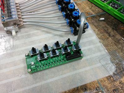
I designed my and assembled my own PCB, because I wanted to learn a bit more about PCB design, but you can purchase MOSFET and optocoupler breakout boards on the Internet quite easily.

Pressure sensors #
Sometimes it's also useful to know what the pressures are in your system, for example if you want to control the pressure in each channel. Unfortunately, cheap pressure sensors are quite hard to use. They're usually a strain gauge in a Wheatstone configuration, so you need an instrumentation amplifier to interface with them.
Sensors with integrated amplifiers cost a bit more, but they'll give processed analog or digital outputs, which are much easier to work with. The prices and availability seem to change all the time, so I won't even try to make a suggestion, I'll just explain my decision process.
I knew I wanted at least 8 pressure sensors, and I preferred to interface with them digitally. Digital pressure sensors come with either I2C or SPI buses. It seems like I2C would be the way to go when you want to have so many of them on one line, until you realise that they have a hardwired I2C address, and the manufacturer only offers three different options. So SPI it was.
I used two sensors, both made by Honeywell. I started with ABPLLNN015PGST5, which is a 15 PSI gauge pressure sensor with SPI output. They were the cheapest ones I could find, at £8 a piece, and worked quite well. However, later on I got more funding, so I moved to HSCDAND030PGSA3, which cost £20. They can go up to 30 PSI, have much nicer ports (with a proper barb to retain the tubing), and come in a DIP package. The cheaper ABP sensors came in an awkward SMD package, and I had to make up tiny adaptors to mount them on a breadboard. Since these things are quite expensive, you may want to reuse them for different projects. The DIP version can be simply put in a socket for easy removal.
I, again, designed a PCB to hold all my sensors. Because some sensors come in 5V, and some in 3.3V versions, I also added a bidirectional voltage level shifter to each channel, so that I could use a 5V microcontroller with a 3.3V sensor and vice versa. I put the sensors in sockets and used some hot glue to make sure they'll stay in place. Of course, none of this is necessary, you could just quickly hack something on a bit of perfboard.
Software #
Software to control the board can be as simple or as complicated as you need it to be. You can use your Arduino Blinky sketch to switch valves, but I needed something a little more sophisticated.
Controlling the Arduino from my computer #
My machine learning code was written in Python, so I wanted to be able to control the valves from Python on my computer. I used the CmdMessenger project and its PyCmdMessenger counterpart to talk to the Arduino. Initially, I used XBee modules to make the communication wireless, but then I realised that they're way too slow for my needs, so I ended up using a Teensy with its USB 12Mbit/sec transfer rate.
I wrote a simple live plotting application using pyqtgraph, which lets me monitor all parameters of my robot in real time.
In the video you can also see outputs from the tracking system I used to get the position of the robot, and from the IMU I used to get its orientation in space. I'll not be explaining those here.
Talking to pressure sensors #
There is no 'official' library to talk to the Honeywell pressure sensors through SPI, so I wrote my own, but then I realised that there are a lot of identical ones on the Internet.
Switching valves #
The simplest way to switch valves is to simply turn them on and of completely. This works for a lot of things, but it doesn't allow us to control the pressure in each channel separately. We can, however, pulse-width-modulate the valves (switch them on and of very fast). The pressure in the robot's joint will be changing slower than the switching frequency, and we can set the pressure to anywhere between 0 and 100% of the supply pressure. However, this is a bit tricky to control reliably.
Filtering the input signal
First, we need to figure out a way to read the average pressure in the channel. I did it with a simple exponential-moving-average digital filter. It removes the high-frequency oscillations from the pressure signal, and leaves only the average pressure level.
UPDATE: Now, after reading a Digital Signal Processing book, I know that a moving average filter is not the best thing for this application. You should really use an IIR (Infinite Impulse Response) notch or low-pass filter tuned to remove the switching frequency.
Adjusting pressure
Then, we need to adjust the pressure in the line. I implemented a simple
proportional-integral controller for that purpose. My library completely abstracts all those things
from the user, they use the setPressure(int channel, float pressure) method,
and it (mostly) just works.
Putting it all together #
Now we have all the bits we need to put together a working system. Let's connect them.
Layout #
To keep things neat, I laid all my components on a piece of laser-cut acrylic. I tapped the holes with an M3 thread and mounted all the PCBs on standoffs.

Electrical connections #
I used IDC connectors (the ones used on old hard drives) to keep my wiring compact. I put my microcontroller in a socket on a bit of perfboard, so that I could solder all connections in place.

Pneumatic plumbing #
As with everything pneumatic, there are a lot of functionally equivalent, competing standards on how to connect things together. I like push-in fittings, so I went with those. I used 6mm OD (outer diameter) polyurethane tubing to connect everything, because the barb ports on my pressure sensors were sized for that. In retrospect, I shold have gone with 4mm OD tubing with adaptors for the pressure sensors. 6mm tubing is way too big for the flowrates I was interested in, and quite rigid, which makes it hard to work with.
You can see how I connected everything on the picture below:

I bought some 6mm push-in tees and used 3D printed brackets to mount them on the edge of the board. They serve double duty, directing air to the pressure sensors, and as nice sturdy output ports for plugging the robot's joints into.
I used 2.5mm OD, 1.5mm ID silicone tubes to deliver air to my robot. They are very flexible, which makes it easier for the robot to tug them along. I also 3D printed some adaptors to connect the silicone tubing to the thick polyurethane one, but I'm sure those can be bought as well.
Finish #
I glossed over many details, but it should be a decent starting point for people looking to build their own pneumatic control board. I'm considering publishing my code and PCB design files, but they're in a bit of a mess now. If enough people will express interest, I'll find some time to clean everything up.
- Next: #hot16challenge2 graphed